

A Polymer Process Engineering & Training Company Home of the CRD Mixing Screws
|
|---|
By: Dr. Chris Rauwendaal
Rauwendaal Extrusion Engineering, Inc.
Los Altos Hills, California 94022 - USA
Introduction
The screw of the plasticating unit of an injection molding machine (IMM) typically consists of a single stage, single flighted conveying screw with a non-return valve at the end. Mixing sections are usually not incorporated into the screw design. One reason for this is the fact that most plasticating units a relatively short; the typical length-to-diameter ratio is 20:1 in IMMs. This does not leave much space to incorporate a mixing element. Another reason may be the mistaken belief that mixing is not very important in the injection molding process.
A convenient method to improve the mixing capability of the plasticating unit of an IMM is to design the non-return valve (NRV) such that it has mixing capability. Such a dual-purpose NRV allows an increase in mixing capability without affecting the melting and conveying capability of the plasticating unit. This paper will describe a NRV mixer based on the CRD mixing technology developed for single screw extruders.
Background
In polymer mixing we usually distinguish between distributive and dispersive mixing. Distributive mixing aims to improve the spatial distribution of the components without cohesive resistance playing a role; it is also called simple or extensive mixing. In dispersive mixing cohesive resistances have to be overcome to achieve finer levels of dispersion; dispersive mixing is also called intensive mixing. The cohesive component can consist of agglomerates where a certain minimum stress level is necessary to rupture the agglomerate. It can also be droplets where minimum stresses are required to overcome the interfacial stresses and deform the droplet to cause break-up.
Dispersive mixing is usually more difficult to achieve than distributive mixing. Single screw extruders are generally considered to be poor dispersive mixers while twin screw compounding extruders have much better dispersive mixing capability. However, when we analyze the mixing process in co-rotating twin screw extruders (1), it is clear that the main mixing action does not occur in the intermeshing region but in the region between the pushing flight flank and the barrel. This is particularly true when the flight helix angle is large as it is in kneading disks. This being the case, there is no reason that the same mechanism cannot be used in single screw extruders.
The reason that twin screw extruders make good dispersive mixers is that the space between the pushing flight flank and the barrel is wedge shaped and thus creates elongational flow as the material is force through the flight clearance. Shear flow is not very efficient in achieving dispersive mixing because particles in the fluid are not only sheared they are also rotated, see figure 1 top. In elongational flow particles undergo a stretching type of deformation without any rotation; rheologists call this “irrotational flow,” see figure 1 bottom.
In the past it was considered to be difficult to generate elongational flow in mixing devices. It turns out, however, that this is not the case. The new dispersive (CRD) mixers developed by Chris Rauwendaal (2-4) create elongational flow two ways, see figure 2. By using a slanted pushing flight flank so that the material is stretched as it is forced through the flight clearance and by using tapered slots in the flights. The tapered slot accelerates the fluid as it flows through the slots and thus creates elongational deformation. The dashed arrows in figure 2 indicate the screw velocity, the solid arrows indicate the melt velocity relative to the screw.
The tapered slots in the flights serve to increase distributive mixing as well as dispersive mixing. If the material is not randomized in its passage through the mixer, only the outer shells of the fluid will be dispersed leaving the inner shells undispersed (5). Therefore, it is critical to incorporate both distributive and dispersive mixing ability within the mixer.
The initial design of the CRD mixer (2) was developed using the concept of the passage distribution function (6), while the final geometry was developed using a detailed three-dimensional flow analysis. The 3D flow analysis was performed using BEMflow (7), a boundary element flow analysis package originally developed at the University of Wisconsin, Madison by Professor Osswald and co-workers. The BEM analysis allows a complete description of flow, so that the stresses, the number of passes over the mixing flights, the number of passes through the tapered slots, residence time, etc. can be quantified for a large number of particles. The CRD mixer may well be the first complex mixing device developed solely based on engineering calculations and computer modeling.
Application to Injection Molding
Mixing is not only important in extrusion, it is equally important in injection molding. CRD mixing elements can be added to an injection screw. Most injection screws have a non-return valve (NRV) at the end of the screw to prevent the molten plastic flowing back into the screw during injection. It is possible to incorporate mixing capability into the NRV to combine two functions within one device. Since the NRV is short, there is little room available to incorporate mixing capability into the NRV. The slide ring NRV is the most suitable with respect to adding mixing capability.
The action of the ring check valve is illustrated in figure 4. When the screw rotates, plastic is conveyed forward, melted, and mixed. The plastic melt accumulates at the discharge end of the screw and pushes the screw back against a controlled pressure. As the screw moves backward, the check ring is dragged to the most forward position against a stop at the end of the screw, see figure 4a. The stop is usually a star shaped shoulder with four to six points. When the check ring rests against the stop plastic melt can flow through the valve.
When the screw moves forward, the check ring is dragged to the most rearward position against the check ring seat forming a seal, see figure 4b. In this position the valve is closed and the plastic melt is thus prevented from leaking back into the screw channel during injection. Because of the relative movement between the check ring and the stop, stops will wear over time and eventually have to be replaced.
Mixing capability can be designed into the slide ring valve by locating mixing pins on the inside of the slide ring as shown in figure 5. The pins are elongated in the axial direction to achieve an acceleration of the fluid as it is passing between two pins. The resulting elongational flow results in effective dispersive mixing. The same elongated pins are also located on the outside of the stop, resulting in a second exposure to elongational flow with further dispersive mixing action. The large number of pins located on the slide ring and stop induce a large number of splitting and reorientation events, resulting in efficient distributive mixing action. The CRD NRV provides a convenient and cost efficient method to improve the mixing capability of injection molding screws. Good mixing action can be incorporated simply by exchanging the conventional NRV with a CRD NRV.
Experience from the Field
As of November 1999 over forty extruders are running with CRD mixers. The current applications are color concentrates, foamed plastic, post-consumer-reclaim with calcium carbonate, medical applications, heat shrinkable tubing, carbon black dispersion in polyolefins, and blown film extrusion of low melt index metallocenes. All current applications are on single screw extruders in sizes ranging from 19 to 200 mm (0.75 to 8.0 inch). Three screws are being manufactured for injection molding and one set of screws for twin screw extrusion.
In the manufacture of color concentrates it was possible to produce even the most difficult material, phthalate blue, with good quality using a single screw extruder. The foamed plastic application polystyrene was foamed with a physical blowing agent carbon dioxide, a demanding application requiring very good dispersive and distributive mixing. The foamed product was found to have uniform cell size and excellent surface quality, while the extrusion process was very stable with respect to melt pressure and temperature. In the blown film application major problems were poor film quality and the inability to feed more than 3% fluff with the virgin plastic without generating gels in the film. The CRD mixing screw was able to improve film quality and handle up to 12% fluff without generating gels.
The good results with respect to gels indicate that elongational mixing devices can effectively disperse gels as opposed to shear mixing devices. Luciani and Utracki found similar results in experiment using their extensional flow mixer (9). The experience from the field was obtained with a fifth generation mixing device, the CRD5, see figure 3. This mixer has four parallel flights with tapered slots in the flights. Each wiping flight segment is followed by three mixing flight segments. Tapered slots separate the flight segments. The wiping segments are offset such that the mixer wipes the entire barrel surface. Complete wiping of the barrel surface is important to achieve efficient heat transfer between the plastic melt and the extruder barrel.
Conclusions
Mixing devices that split and reorient the fluid while generating strong elongational flow can achieve both efficient distributive and dispersive mixing. CRD mixers have proven their effectiveness in extrusion (2-4); however, their use is not limited to single screw extruders. The same mixing devices can be used in injection molding. Perhaps the most convenient method to enhance the mixing capability in injection molding is to design mixing elements into the non-return valve.
This paper describes a slide ring valve/mixer based on the patented mixing technology (8). The slide ring has multiple internal grooves that are tapered while the nose-piece has external, tapered grooves. The tapered grooves are formed by elongational pins. The pins split and reorient the fluid thus causing efficient distributive mixing. The tapered grooves accelerate the fluid and cause elongational flow with efficient dispersive mixing.
The high mixing efficiency of the CRD mixer is due to the generation of strong elongational flow and the fact that all fluid elements make multiple passes through the high stress regions. Elongational flow not only achieves more effective dispersion, it also creates less viscous dissipation than shear flow. As a result, the power consumption and temperature rise in the CRD are less than in mixing devices that rely on shear flow.
The CRD valve/mixer is easy to manufacture and can be mounted on existing injection screws. Since the non-return valve on many injection screws is removable, it is very easy to replace a conventional valve with a CRD valve/mixer. As a result, the change-over can be done in a short period of time. Actual results of the NRV mixer obtained from injection molding trials will be presented at the ANTEC meeting.
References
1. “Polymer Mixing, A Self-Study Guide,” C. Rauwendaal, Carl Hanser
Verlag, Munich (1998)
2. “A New Dispersive Mixer for Single Screw Extruders,” 56th SPE ANTEC, Atlanta,
GA, 277-283, Chris Rauwendaal, Tim Osswald, Paul Gramann, and Bruce Davis
(1998)
3. “Experimental Study of a New Dispersive Mixer,” Chris Rauwendaal, Tim
Osswald, Paul Gramann, Bruce Davis, Maria del Pilar Noriega, and O. A. Estrada,
57th SPE ANTEC, New York, 167-176 (1999)
4. “Design of Dispersive Mixing Sections,” Chris Rauwendaal, Tim Osswald,
Paul Gramann, and Bruce Davis, International Polymer Processing, Volume 13,
pp. 28-34 (1999)
5. “Kinematics and Deformation Characteristics as a Mixing Measure in the
Screw Extrusion Process,” T.H. Kwon, J.W. Joo, and S.J. Kim, Polym. Eng.
Sci., V. 34, N. 3, 174-189 (1994)
6. “The Distribution of Number of Passes Over the Flights in Single Screw
Melt Extruders,” Z. Tadmor and I. Manas-Zloczower, Advances in Polymer Technology,
V. 3, No. 3, 213-221 (1983)
7. BEMflow, Boundary Element Fluid and Heat Transfer Simulation Program, ©1996
The Madison Group: PPRC
8. C. Rauwendaal, U.S. Patent 5,932,159
9. “The Extensional Flow Mixer”, A. Luciani and L. A. Utracki, Intern. Polymer
Processing XI, 4, 299-309 (1996)
Figure 1, dispersion in shear and elongational flow
Figure 2, Two methods of creating elongational flow in the CRD mixer
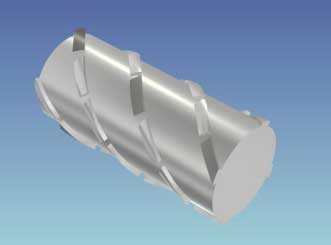
Figure 3, Three dimensional rendering of a CRD5 mixer
Figure 4, The ring valve in open (a) and closed (b) position.
Figure 5, CRD non-return valve for injection molding screws (open position)
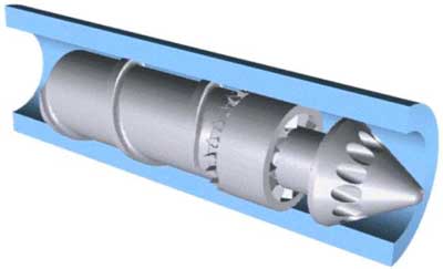
Figure 6, Solid model of CRD-NRV