

A Polymer Process Engineering & Training Company Home of the CRD Mixing Screws
|
|---|
Rauwendaal Extrusion Engineering, Inc.
is pleased to announce the development of the CRD barrier screw; the first
extruder screw that combines the benefits of barrier screws with the superior
mixing characteristics of the CRD mixer. In barrier screws the barrier flight
separates the solid bed from the melt pool. The barrier flight divides the
main channel into a solids channel and a melt channel. The solids channel
reduces along the length of the barrier section while at the same time the
melt channel increases. As a result, all of the plastic melt is forced over
the barrier flight into the melt channel. At the end of the barrier section
the solids channel disappears leaving no room for
unmelted plastic. This gives the barrier screw the following benefits:
1. Practically no unmelt possible beyond the barrier section
2. Generally more stable than simple conveying screws
3. All of the plastic melt passes over the barrier flight and is exposed to
a certain amount of dispersive mixing
A schematic of a barrier screw is shown in the figure below.
Figure 1, Illustration of barrier screw
The unique feature of the CRD barrier screw is that
the barrier flight is designed to
generate elongational flow as the plastic melt passes over the barrier flight.
This can be
done by making the pushing flight flank of the barrier flight curved or slanted.
This creates a wedge-shaped region between the barrier flight and the barrel in
which the plastic melt is accelerates as it passes over the barrier flight. The acceleration
creates the elongational deformation in the plastic melt.
Conventional flight CRD flight geometry
Figure 2, Standard barrier flight (left) vs. CRD barrier flight (right)
Figure 2 shows a conventional barrier flight geometry (left) next to a CRD
barrier flight geometry on the right. The benefit of the CRD barrier flight geometry is
improved dispersive mixing and reduced energy dissipation, which will result in lower
melt temperatures.
A drawback of barrier screws is that their distributive
mixing capability is rather poor. As a result, the CRD barrier screw
will generally be equipped with a CRD mixing section downstream of the barrier
section to improve both dispersive and distributive mixing.
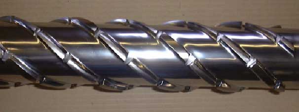
Figure 3 shows a picture of a multi-flighted CRD5 mixer.
Figure 3, CRD 5 mixing section
The multi-flighted CRD mixers are designed to expose
all the material to multiple high stress events to achieve a fine dispersion.
Conventional mixers, like the Maddock, expose the material to only one high
stress event, thus limiting the mixing efficiency. Another
advantage of the CRD mixer is that it is designed to have forward pumping
capability. As a result, incorporating a CRD mixer does not compromise the
output capability of the extruder. The main benefits of the CRD mixer are:
1. Better dispersive and distributive mixing
2. Reduced barrel pressure fluctuation
3. Reduced melt temperature fluctuation
4. Reduced die lip buildup
5. Reduced power consumption
6. Higher extruder output because of pumping action of the mixer
7. Better output stability and dimensional control
8. Better and more consistent product appearance
9. Reduced melt temperatures (less chance of degradation)
10. The CRD mixer can disperse gels; shear based mixers cannot disperse gels
The CRD mixer was first introduced into the plastics industry in October 1998. At this time over 100 CRD extruder screws from 18-mm up to 200-mm in size are successfully used in various applications – the first customer is now running 25 CRD screws! The CRD mixers are used in single screw extruders, twin screw extruders, injection molding machines, and blow molding machines. Some of the applications are color concentrates, foamed plastic, post-consumer reclaim with filler, medical applications, heat shrinkable tubing, blown film extrusion, and reactive extrusion.